
As IoT and robots have become more popular, they are now being integrated into our homes. Developers face the challenge of meeting all certification authority requirements to ensure compliance with laws. The standard IEC60335-1 is mandatory for all consumer products entering the mass market. For autonomous equipment that is not supervised, such as robots (vacuum cleaners and similar), or motor-operated IoT controls (solar controllers for pet food, window controllers, etc.), it is essential to prevent DC motors from overheating. Regulation IEC60355-1, Chapter 19.11, outlines the compliance requirements for a single failure in electronics during regular operation. This article uses a power switch solution based on high-voltage GreenFET to verify the current sensor’s functionality and, if needed, turn off the power.
The architecture of the system
Most systems today have a microcontroller that executes an application to implement the functionality. The controller can also implement safety-related functionality when the system contains potentially dangerous components for end users, such as motors or linear drives.
Standards such as IEC60335-1, which applies to home appliances, define the requirements of consumer goods. Figure 1 depicts a prototype DC motor driver circuit architecture. A motor controller is being used here to drive a DC Motor. The motor controller receives power from a power unit via the backup power switch. This serves as a secondary deactivation protection layer. Buttons can be used to save energy by turning off motor controllers when they are not being used.
It is essential to have a validating capability for the sensor subsystem and a backup switch to deactivate the motor drive in an emergency. In this case, the SLG59H1x family of High Voltage GreenFETs’ current monitor output can be instrumental.
Table 1 summarizes High Voltage GreenFET parts with the current monitor output capabilities by extracting information from the selection guide [ GreenFETTM Low RDSON Selector Guide]. It may be helpful to have the FAULT output, which allows you to use the integrated protection against overcurrent, voltage, and temperature. All switches share the STQFN-18 package, which is only 1.6mm x 3.00mm. This saves space on the PCB. The PCB layout must be more carefully considered to meet cooling requirements.
High Voltage GreenFET Concepts and Capabilities
Renesas High Voltage GreenFET combines MOSFET with a driver to create a load switch. It is also a device that is fully protected against overvoltage and overcurrent. It can be externally accessed to access its extended sensing capabilities. Figure 2 shows a conceptual block diagram for the High Voltage GreenFET (Datasheet) in an application diagram.
The SLG59H1120V comprises an N-MOSFET in switching mode, driven by a charging module and a linear ramp control unit. The state machine determines the MOSFET’s state based on the ON input and considers possible overrides by protection units. VIN OVLO is adjustable via SEL0/SEL1 Overvoltage Lockout. Overcurrent is adjustable using the resistor settings at RSET input. MOSFET current is also mirrored on IOUT output and can be converted into a voltage by a pull-down resistance. This can then be used to control the host system. FAULT displays the system’s current state and makes it easy to detect any protection events during system operation. All these features result in a reduction of BOM components and costs, as well as an increase in system reliability.
Application Circuits and Example Module
Figure 3 shows the DC motor driver used in this article. U4 is the DC motor driver shown here. Commonly, the A4950 driver or another pin-compatible one is used. The shunt resistor R7 is used for current measurements, while the U2A will amplify its voltage drop. U3 SLG59H1120V, connected to the host, provides ON/OFF, current sensing, and fault output functionality. LDO U1 provides a secondary 3.3V power supply to OPAMP U2A and sets the motor driver U4 reference voltage. The second OPAMP U2B can be bypassed and used elsewhere. LED D2 shows the state of the power supply taken from node 3V3, while D3 displays the form of power for the motor driver.
The filtering capacitor C3 is added to the host system capacitors at 470uF. (This was placed on the experiment module as well). The high starting current of a DC motor can easily trigger an overcurrent on U3. Therefore, an additional 220uF capacitor was added to the power input on U4. The module has two thresholds for overcurrent events triggered by hardware. R5 sets the first, connected with the RSET pin, and adjusted to 5 A. The second is for U4, developed by applying 3.3V to the VREF pin.
Hardware limits protect electronic components against overcurrent. The power switch U3 can drive more than one motor driver. Robotics is an example of a field where it’s normal to have more than two motors. It makes sense to set higher limits to ensure the power switch does not throttle current.
Safety-related limits are set lower in the firmware to prevent current limitations from the hardware from being below safety limits than the maximum current provided by motor driver U4. It also ensures that the order in which overcurrent protection is triggered will be clear, with firmware being the first, the motor controller, and finally, the power switch. The hierarchical system recommended for a safety architecture is shown in Figure 5. The DC motor current limit can be determined by measuring the winding temperature of the motor. At the same time, it is stalled and compared that temperature with the value given in IEC 60335-1 Chapter 19.7 (Table 2).
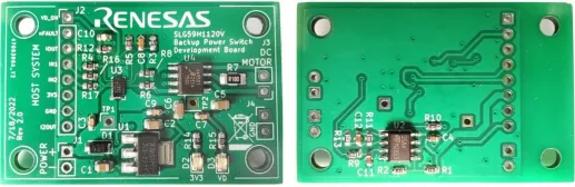
IEC60335 requires two different current sense signals, IOUT and I2OUT, because the standard demands a plausibility test for the sensor system, which is performed by the firmware, comparing two different current measurement signals in the current sensor validation block (see Figure 6). The application circuit was implemented on a PCB as an experimental module for testing and functionality validation. The module can be seen in Figure 4. The module is implemented on a two-layer PCB, with pinout headers that are provided for a DC motor and host system.
Test Setup
For testing the circuit in the application, the host system was simulated through an Arduino-based controller, which was used for the activation/deactivation PWM of the motor, validation of sense, and backup power deactivation in case the main one didn’t work. The tester’s software must comply with IEC60335-1 Annexe R (Software Evaluation), as this was not the focus of the article. However, the principle of operation can be used in real applications without any additional effort.
Test Software Algorithm
Figure 6 shows the Test software algorithm. The operation begins with the activation of VD power by setting VD_ON. The Current sensor block checks if the High Voltage GreenFET IOUT measurement is the same as the measurement from the motor driver I2OUT. In this case, the system is considered to be broken. The driver power will be deactivated, and the system’s state will change to Eternal STOP. All system functions have been deactivated in this state, and an alert has been set. The motor can be operated if the current sensor verification has been successful.