
The James-Webb Space Telescope returned to Earth early this year with some of the most detailed pictures of other galaxies. The Travelling Wave Tube Amplifier, a Vacuum Electron Device (VED), was part of the microwave amplifier system used at the telescope and ground station. The TWTs date back to over 80 years before WWII. Haeff Lindenblad Kompfner and other brilliant RF engineers are credited for the invention and development of this device in the 1930s & 1940s. The use of TWTs grew dramatically in the post-war years when peace reigned. The TWTs were used to create microwave ground relay stations on communication satellites like Telstar, Intelsat, and Inmarsat and to help create today’s global communication networks.
The TWT was also used in deep space probes such as Voyager, Cassini, etc. There are currently thousands of TWTs orbiting the Earth and also in satellite ground stations. TWTs also play a significant role in electronic warfare systems, including radar and guidance systems. The dominant suppliers are Thales, Stellent NEC Teledyne E2V, and others. According to current estimates, the TWTA market is valued at $1B with a single-digit percentage annualized growth.
Operation Principle of TWT
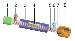
The TWT is a beautiful device because of its close interaction with the RF to be amplified. In Figure 1, a simplified version of a standard machine, the Helix TWT, is shown.
The electron wave is produced in a cathode heated to temperatures of around 1000oC. The tube has an Ultra High Vacuum of 10-8 Torr. A beam is created by an HV (typically 4-120 kV) applied between the cathode and the anode. The focus or control grid guides the shaft to the next part of the device. The Electronic Power Conditioner (EPC), which converts satellite bus voltage into the regulated high-voltage needed by the electron source, is a device that uses the Electronic Power Conditioner. In the Slow Wave Structure (SWS), the RF input is slowed using the Helix to act as a delay. The goal is to match the wave speeds of the electron beam with the RF wave. The SWS uses a periodic permanent magnet to focus the electron beam toward the device axis.
The interaction of the electron with the Helix creates a bunching of electrons and a positive feedback mechanism, which amplifies RF waves. This is because the lost electron beam’s momentum transfers to the RF signal through the principle of momentum conservation. The Helix is a low-impedance path that can be made of low O2 Cu. Separate helix sections can be maintained using attenuators to prevent reflections and oscillations.
3D electromagnetic simulations are used to optimize the Helix and cavity. For example, the pitch can be varied along the tube’s length to match changes in electron wave velocity. BeO ceramic rods can be used to support the helix and transfer heat. The collector is the last stage, where the remaining energy from the electrons is converted into heat. Creating a multi-stage, depressed collector allows electron energy recovery while improving efficiency. The device’s linear range allows for low-distortion amplification of small signals. The device is operated below its saturation power level using an Output Back Off. C/3IM displays the S/N for the 3rd Harmonic Wave. Figure 2b is an example plot showing efficiency and power as a function of frequency for a TWTA in the Ku-band. Linearizers are compatible with TWTs, as illustrated in Fig1, a Linearizer Channel Amplifier. The LCAMPs have a hardware or digital pre-distorter which can compensate for the non-linearity of the tube and provide a constant output or gain. Table 1 provides some basic specifications of TWTAs from one manufacturer for the Ku and Q bands.
Space TWTAs are made by hand and require several months of precision work. They must be tuned at different temperatures, including room temperature and hot and cold. The cost of a TWTA can vary from several thousand dollars to hundreds of thousands.
TWTA Advantages and Comparisons with Solid-State Power Amplifiers
The low noise figure and high bandwidth of TWTAs were two essential features that made it famous in the early days. TWTAs are superior to Klystrons, which have a limited BW and are sensitive to the spacing of their structural elements. They also provide higher gains (up to 70db) and peak power ranging between 10’s W and several 1000’s kWs. Coupled cavity TWTAs can deliver higher capacity at lower BW than Helix TWTAs. SSPAs, especially those based on GaN, have replaced TWTAs in specific traditional TWTA applications. SSPA is now used in microwave relay stations and Low Earth Orbit Satellites such as OneWebTM.