
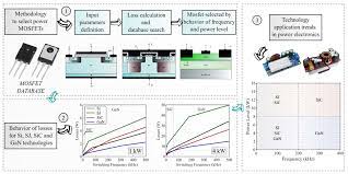
Since their first commercialization in the late 90s, super junction silicon MOSFETs have succeeded in power device applications. In this article, we will discuss the performance and application of Wide Band Gap (WBG), Silicon Carbide (SiC), as well as Gallium Nitride (GaN).
SJ MOSFET
Examine the elements that contribute to the on-state resistivity (R DSON), shown in Figure 1, to understand the benefits and concept of an SJ MOSFET.
For a device with a rating of 30V, the approximate contribution from the drift region to R is 30%. This region will get thinner and less doped as the voltage rating increases. This region can represent more than 95% of the total R DSON of a 600V device. The SJ concept uses the idea of charge balancing to resolve this issue. Figure 2 illustrates the deep p-doping columns in the drift area to offset the higher doped n regions (compared to the planar MOSFET) through which electrons travel. Creating a space-charge depletion region in the Off state leads to a uniform distribution in the electric field and, therefore, a higher breakdown voltage.
As discussed in the next section, SJ devices can be reduced significantly for a given DSON R. This leads to improved switching behavior. The Si limit was exceeded by SJ devices for R DSON in 1979, based on the 1-D Poisson theory 3. To reduce the R, DSON for SJ devices using a 2D-Poisson solution is possible by increasing doping concentrations and decreasing the pitch shown in Figure 2.
Process/Device Challenges
In Figure 3, two distinct methods of making SJ MOSFETs can be seen. Figure 3 shows two different ways of making SJ MOSFETs. The picture on the right shows a deep-trenched approach, where regions designated for p-columns have been etched out and filled.
These two methods each have their unique advantages and disadvantages. Multi-epitaxial approaches can be used to adjust doping levels vertically. However, the out-diffusion creates spherical areas that are difficult to balance. The trench method has advantages in lateral control, smoother columns, and a smaller pitch. However, the process of etching and completing the column is more challenging. The device challenges included improving avalanche performances. Avalanche events can affect the charge balance and lower the breakdown voltage. This is not desirable for reliability. In RDSON, avalanche ruggedness is a trade-off. A large junction area is another intrinsic feature of an SJ device, which leads to a high Reverse Recovery Charge (QRR), limiting its use in applications that require 3rd Quadrant operation.
Performance and Characteristics of Si SJ MOSFET
The specific on-state resistivity of a non-SJ vertical unipolar MOSFET can be expressed in the following way:
Here, BV represents the breakdown voltage. you mean channel mobility. e represents the permittivity. Ec is the critical electrical field. This changes to:
As shown in Figure 2, Cp is the pitch of each column. Equation 2 indicates that SJ MOSFETs can have R and DSON much smaller than Silicon power MOSFETs. This is shown in Figure 4, which compares R DSON of Si SJ MOSFETs with other technologies at Cp = 1um. For example, a 600V SJ Si MOSFET has a 60x improvement in R DSON compared to a conventional Si MOSFET.
Another key advantage is the nonlinearity of the output capacitance (COSS) versus the VDS drain voltage. Figure 5 shows the C and OSS behaviors for successive Infineon’s CoolMOSTM SJ technology generations. The C and OSS are more apparent when the cell pitch Cp is reduced. A plate capacitance model at high VDS approximates the C and OSS. In this case, the plate distance represents the width of depletion space charges. As cell pitch decreases, this lateral depletion will occur at lower voltages. As Cp decreases, the SJ die size required for a given R is smaller.
The switching energy loss for a hard-switching converter strongly depends on the stored energy in Eoss capacitance, which depends on C CSS(er) capacitance. C and OSS have a strong nonlinearity, which allows for a near-lossless switch-off. The MOS channel can be turned off within the time needed to charge the output capacitance. Table 1 compares characteristics of conventional 600V Si MOSFETs and SJ 600V SI MOSFETs with similar DSON R. The SJ device shows improvements between 15-25% on critical parameters like total gate charge (Qg), Miller gate-drain capacitance Qgd, reverse recovery charge Qrr and Eoss. The SJ device’s avalanche rating EAS is lower in this case due to the smaller die. In many high-power applications, the overvoltage ability is more critical so that clamping circuits have enough margins to trigger.
The reduction of gate charges has several benefits. This allows faster switching of devices for a gate driver, or, conversely, it can reduce total power consumption by using a driver with a lower current. The reverse recovery charge (Q ) RR is another critical improvement path in SJ devices. This is especially important in applications requiring continuous commutation in the 3rd Quadrant, like totem-pole PFCs. In these applications, stand-alone Si SJ MOSFETs are not recommended. Instead, they should be paired with a Schottky Barrier Diode with no Q or RR. Or, replace the Si SJ device with a WBG like SiC or GaN. The gap between Q and RR has been narrowed by improvements in the SJ processes to achieve faster reverse recovery of the body diode.