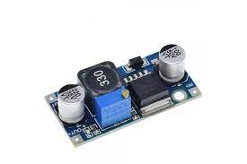
In the industrial, medical, and even domestic fields, the need to convert DC voltages into other DC voltages is often at the heart of many applications. DC-DC converters are devices that can be more or less complex. They change DC voltage from one level to another. The Voltage can change in an increasing or decreasing fashion. This chapter will examine the most commonly used approaches.
Variating the Voltage from a Direct Current source – DC-DC converter
The transformer’s simplicity is one reason electricity is distributed in alternating form at home. It is possible to safely and efficiently raise or lower alternating mains voltage with a transformer. Unfortunately, DC voltage is more complicated. The transformation of DC voltage is much more complex and requires unique methods, strategies, and electronic components. Conversion of DC voltage to another DC voltage can be used for various power applications, such as controlling electric motors and other applications that require constant rotational speed while maintaining torque and force parameters. DC to DC conversion makes it easy to create sophisticated power supplies that can work with different voltages depending on the user’s requirements.
The Buck (Step-Down)
DC-DC switching systems use electronic components and switches that are driven appropriately to store energy. This allows it to be converted. Step-down or buck converters are DC-DC power converters that reduce the input voltage to provide a lower output voltage. Modern technology encapsulates all the complex circuitry in one enclosure. Lowering the voltage input using a power resistor is possible, but this would waste a lot of energy in the form of heat. This would result in a very low efficiency. The switching circuit is based on an electronic switch, such as a Mosfet, BJT, or similar device, that switches ON and off at a high frequency. The switching frequency must be higher than ultrasonic frequencies (>20kHz).
This Voltage is determined by the duty cycle, which is between 0% and 100% (PWM). This Voltage depends on the duty cycle (0% and 100%). This Voltage will be equal to the following:
Step-down DC to DC Converter with Resistor & Inductor as the Load
Figure 2 illustrates a generic schematic of a step-down system and its operating principle using an LC-type load. This DC-DC converter provides an output voltage lower than the input voltage. It is mainly composed of a Mosfet SW switch and a diode. The output filter consists of an inductor (L), a capacitor (C), and a load resistance R. The operation of the circuit is effortless. A DC voltage of V powers the course. The electronic switch produces a rectangular signal that has a voltage value greater than zero and a duty cycle parameter. The output voltage is an average between 0V and Vs. according to the parameters defined by the ON percentage of the signal. The oscillograms show the following signs:
- v (in): is the DC input voltage that supplies the entire conversion circuit.
- (SW) v(SW) is a rectangular signal (pulse-train) provided by the system controlled via the electronic switch.
- (v): represents the signal at the diode ends. As can be seen, it is affected by peaks, oscillations, and interference (EMI).
- v (out): indicates that the output signal is lower than the input. The oscillations are deliberately emphasized in the figure. This problem is usually reduced by using a large output capacitor.
- Now we can observe how the electronic components perform in two phases of the dc-dc conversion operation. When the switch is turned ON and OFF:
- When the switch closes, the current flows commonly through it and not through the diode, which is inversely polarised. This current charges the capacitor. The button is then in normal conduction and the current flows generally from the voltage generator towards the load.
- As soon as the switch is opened, the inductor reverses Voltage at both ends of the coil and puts the diode in conduction. This component suppresses any surges which may occur as the switch opens. The button is not conducting, but the load current passes through the diode.
- The output current is roughly equal to the average current of the inductor. During the “ON,” the MOSFET current will equal the average inductor current plus a ripple. During the “OFF,” the diode’s current equals the total of the middle inductor current plus the wave. The efficiency of the circuit would be 100 percent if the inductor, capacitor, and other components were perfect. In reality, the efficiency is 94%. The signal’s duty cycle is a critical factor in the efficiency of the circuit. When the output voltage is lower than the input, there is a large current at the switch. This results in wasteful energy use. The graph in Figure 3 shows that when the duty cycle is low, so will the converter’s efficiency. It is best to avoid designing converters with a duty cycle below 20% to achieve high reduction ratios. The two scales in the graph represent percentages.

